Showing posts with label HomeAssistant. Show all posts

Tuesday, September 5, 2023

Monitor solar heating with ebusd

I have Wolf flat-plate collector on my roof to heat water in the bottom of the warm water tank. There is simple monitoring (Wolf BM Solar) which shows whether heating is on and temperatures on the collector and in the tank. I wanted to see this data in my Home Assistant.

Wolf does not support OpenTherm but eBUS. After short searching on internet, I've found eBUS adapter which can monitor/control eBUS devices (mainly boilers). Delivery took about 2 months but finally I have it now.

First steps with the adapter are well described. Yet I had some issues:

  • flashing and accessing web interface (easi) was fine
  • I've struggled with easi authentication - after entering credentials, accessing it from the same browser still worked. Only accessing it from another browser timed out and I don't see a way how to enter credentials (passing them in the url does not work). I will dig deeper into it later. UPDATE: it's fixed by 2023-09-03 firmware.
  • I run ebusd on my Turris router in docker. For some reason, which I don't remember now, all my docker containers had forbidden access to internet. HomeAssistant is fine with it but ebusd needs to download configuration files and it took me a while to find out why requests for configuration were failing.

The biggest issue was with configuration. My Wolf is not supported out of the box. Following docker readme, I have run the following command:

root@turris:~# docker run --rm -it -p 8888 john30/ebusd --scanconfig -d ens:192.168.1.87:9999 --latency=20
2023-09-03 18:07:50.453 [main notice] ebusd 23.2.23.2 started with auto scan on device: 192.168.1.87:9999, enhanced
2023-09-03 18:07:51.734 [bus notice] device status: resetting
2023-09-03 18:07:51.735 [bus notice] bus started with own address 31/36
2023-09-03 18:07:51.740 [bus notice] signal acquired
2023-09-03 18:07:52.240 [bus notice] device status: reset, supports info
2023-09-03 18:07:52.355 [bus notice] device status: extra info: firmware 1.1[380f].1[380f], jumpers 0x0f
2023-09-03 18:07:58.939 [bus notice] new master 71, master count 2
2023-09-03 18:07:58.939 [update notice] received unknown BC cmd: 71fe50180e0080008000800080008000800000
2023-09-03 18:08:02.009 [bus notice] scan 76: ;Kromschroeder;  ;0227;-
2023-09-03 18:08:02.009 [update notice] store 76 ident: done
2023-09-03 18:08:02.009 [update notice] sent scan-read scan.76  QQ=31: Kromschroeder;  ;0227;-
2023-09-03 18:08:02.009 [bus notice] scan 76: ;Kromschroeder;  ;0227;-
2023-09-03 18:08:02.219 [main error] HTTP failure: receive error: 404 Not Found
2023-09-03 18:08:02.219 [main error] unable to load scan config 76: list files in kromschroeder ERR: element not found
2023-09-03 18:08:02.219 [main error] scan config 76: ERR: element not found
2023-09-03 18:08:13.921 [update notice] received unknown BC cmd: 71fe50171000011a016b0200800080008000800080
2023-09-03 18:08:28.879 [update notice] received unknown BC cmd: 71fe50180e0080008000800080008000800000

I connected to docker shell and get more info:

root@600974f7960e:/# ebusctl i
version: ebusd 23.2.23.2
device: 192.168.1.87:9999, enhanced, firmware 1.1[380f].1[380f]
signal: acquired
symbol rate: 20
max symbol rate: 47
min arbitration micros: 4
max arbitration micros: 4
min symbol latency: 17
max symbol latency: 19
scan: finished
reconnects: 0
masters: 2
messages: 12
conditional: 0
poll: 0
update: 4
address 31: master #8, ebusd
address 36: slave #8, ebusd
address 71: master #9
address 76: slave #9, scanned "MF=Kromschroeder;ID=  ;SW=0227;HW=-"

Using HowTos and Message definition, I was able to decode above unknown messages:

2023-09-03 18:08:13.921 [update notice] received unknown BC cmd: 71fe50171000011a016b0200800080008000800080
2023-09-03 18:08:28.879 [update notice] received unknown BC cmd: 71fe50180e0080008000800080008000800000

root@7e8bde847891:/# ebusctl grab result
71fe50171000010301580200800080008000800080 = 2
71fe50180e0080008000800080008000800000 = 3

There is a master device (id 71) - that's the solar heating. Then there is a slave device (id 76) which is Wolf BM Solar module (it displays data from master). The master broadcasts (BC in log or fe in message) messages. PBSB of messages are 5017 and 5018.

I've searched through ebusd-configuration repo for PBSB codes and found them in ebusd-2.x.x/de/wolf/50.csv.

To be able to use updated configs, I've created ebusd_config folder on turris that is shared to ebusd docker container. Based on unable to load scan config 76: list files in kromschroeder error, I've created kromschroeder subfolder there where I

  • copied ebusd-2.x.x/de/_templates.csv to ebusd_config/kromschroeder/_templates.csv
  • copied ebusd-2.x.x/de/wolf/50.csv to ebusd_config/kromschroeder/76.csv
  • copied ebusd-2.x.x/de/wolf/broadcast.csv to ebusd_config/kromschroeder/broadcast.csv and added 2 lines with missing PBSB codes (changing message type to broadcast b):
    # type (r;w;u;1-9),class,name,comment,QQ,ZZ,PBSB,ID,field1,part (m;s),type / templates,divider / values,unit,comment,field2,part (m;s),type / templates,divider / values,unit,comment,field3,part (m;s),type / templates,divider / values,unit,comment,field4,part (m;s),type / templates,divider / values,unit,comment,field5,part (m;s),type / templates,divider / values,unit,comment,field6,part (m;s),type / templates,divider / values,unit,comment,field7,part (m;s),type / templates,divider / values,unit,comment
    *b,broadcast,,,,FE,,,,,,,,,,,,,,,,,,,,,,,,,,,,,,,,,,,,,,,,,,,,
    b,,betrd,Betriebsdaten des Feuerungsautomaten an den Regler,,,0503,01,status,,UCH,,,Feuerungsautomatstatus,zustand,,HEX,,,Feuerungsautomatzustand,stellgrad,,percent0,,,StellgradKesselleistung (Wolf Gastherme Ersatzwert: FF),kesseltemp,,temp1,,,Kesseltemperatur ,ruecklauftemp,,temp0,,,Rücklauftemperatur ,boilertemp,,temp0,,,Boilertemperatur ,aussentemp,,outsidetemp,,,
    b,,sollw,Sollwertübertragung des Reglers an andere Regler,,,0800,,kesselsolltemp,,temp2,,,Kesselsollwert,aussentemp,,temp2,,,Außentemperatur,leistungszwang,,D1B,,%,Leistungszwang,status,,HEX,,,Status,brauchwassersolltemp,,temp2,,,Brauchwassersollwert,,,,,,,,,,,,
    b,,ertraege,,,,5018,,leistung,,D2B,,,Solarleistung,ertraglow,,UCH,,,ErtragTagLow,ertraghigh,,UCH,,,ErtragTagHigh,ertragsummelow,,UCH,,,SummeErtragLow,summertraghigh,,UCH,,,SummeErtragHigh,ertragsumme,,UCH,,,SummeErtragM,,,,,,
    b,,temp,,,,5017,,pumpe,,UCH,0xbc=off;0xbd=on,,SolarPumpe,,,IGN:1,,,,kollektortemp,,temp,,,Kollektortemperatur,wwsolartemp,,temp,,,WW Solartemperatur,,,,,,,,,,,,,,,,,,
    

I ran the docker again and success:

root@turris:~# docker run --rm -it -p 8888 -v "/srv/ebusd_config:/mnt:ro" john30/ebusd --scanconfig --configpath=/mnt -d ens:192.168.1.87:9999 --latency=20
2023-09-03 21:03:05.609 [main notice] ebusd 23.2.23.2 started with auto scan on device: 192.168.1.87:9999, enhanced
2023-09-03 21:03:05.853 [bus notice] device status: resetting
2023-09-03 21:03:05.854 [bus notice] bus started with own address 31/36
2023-09-03 21:03:05.873 [bus notice] signal acquired
2023-09-03 21:03:06.305 [bus notice] device status: reset, supports info
2023-09-03 21:03:06.473 [bus notice] device status: extra info: firmware 1.1[380f].1[380f], jumpers 0x0f
2023-09-03 21:03:15.326 [bus notice] new master 71, master count 2
2023-09-03 21:03:15.326 [update notice] received unknown BC cmd: 71fe5017100001e000430200800080008000800080
2023-09-03 21:03:16.113 [bus notice] scan 76: ;Kromschroeder;  ;0227;-
2023-09-03 21:03:16.113 [update notice] store 76 ident: done
2023-09-03 21:03:16.113 [update notice] sent scan-read scan.76  QQ=31: Kromschroeder;  ;0227;-
2023-09-03 21:03:16.113 [bus notice] scan 76: ;Kromschroeder;  ;0227;-
2023-09-03 21:03:16.115 [main notice] read common config file kromschroeder/broadcast.csv
2023-09-03 21:03:16.116 [main notice] read scan config file kromschroeder/76.csv for ID "", SW0227, HW65535
2023-09-03 21:03:16.116 [main notice] found messages: 8 (0 conditional on 0 conditions, 0 poll, 4 update)
2023-09-03 21:03:30.288 [update notice] received update-read broadcast ertraege QQ=71: -;0;128;0;128;0
2023-09-03 21:03:45.274 [update notice] received update-read broadcast temp QQ=71: 0;14.00;36.19

Data from master broadcast (temp QQ=71: 0;14.00;36.19) tells me that:

  • 0 - pump is not running
  • 14.00 - collector temperature
  • 36.19 - warm water tank temperature

I'm not interested in ertraege (yield of the solar) - gathering is turned off anyway.

The final command to run ebusd in the background has to use environment variables to set the parameters:

docker run --name ebusd -d -p 9090:9090 -v "/srv/ebusd_config:/mnt:ro" -e EBUSD_DEVICE=ens:192.168.1.87:9999 -e EBUSD_SCANCONFIG= -e EBUSD_CONFIGPATH=/mnt -e EBUSD_LATENCY=20 -e EBUSD_HTTPPORT=9090 john30/ebusd

There are several options how to get data from ebusd to Home Assistant. As I don't use MQTT and I need just 2 values, I've decided to use simple polling via http (that's why EBUSD_HTTPPORT parameter in above command). I've tried to secure it by -e EBUSD_READONLY= but that resulted in failures of reading the configuration (which is actually expected as I have found later).

rest:
  - resource: http://192.168.1.1:9090/data/broadcast/temp
    scan_interval: 15
    binary_sensor:
      - name: Solar - running
        unique_id: solar_ohrev_id
        device_class: running
        value_template: "{{ value_json['broadcast']['messages']['temp']['fields']['pumpe']['value']|int == 1 }}"
    sensor:
      - name: Solar - collector temperature
        unique_id: solar_kolektor_id
        state_class: measurement
        device_class: temperature
        value_template: "{{ value_json['broadcast']['messages']['temp']['fields']['kollektortemp']['value'] }}"
        unit_of_measurement: °C
      - name: Solar - tank temperature
        unique_id: solar_teplota_vody_id
        state_class: measurement
        device_class: temperature
        value_template: "{{ value_json['broadcast']['messages']['temp']['fields']['wwsolartemp']['value'] }}"
        unit_of_measurement: °C

This is graph from today's sunny weather. It's nicely visible how the full tank was heated to over 60°C.

  • red line - collector's temperature
  • blue line - bottom tank temperature
  • orange line - top tank temperature

Sunday, January 8, 2023

Quest for lower electricity consumption - What does burn the heat?

Equipped with long term data, I started performing tests. As described previously, my home setup is not that simple.

Heating pipe for warm water tank is not separated from central heating pipes by three-way valve. When heating up the tank, the pump for tank circle runs and the other two are off. Vice versa when heating the central heating branches.

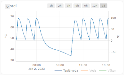
This is the usual temperature graph for a night (that means no warm water concumption):

From 65°C to 50°C in approximately 2,5 hours. The reason for not fully heated tank around 1:00 is there more expensive electric tariff between 1:00 - 2:00 and the boiler is turned off.

Hypothesis
My first idea was the water in tank is cooled by water from the central heating. So I closed valves for a night and checked the graph.


The cooling rate from 65°C to 45°C is the same as for any other night, so cooler water for the central heating is not the culprit. Why the tank cannot keep hot water longer was a mystery...

Culprit
Finding the real culprit required having a beer with neighbors in a pub. More head, the greater knowledge and soon we had a hypothesis that the loss of heat is caused by natural circulation. My warm water tank is in the basement and warm water pipes go through the house and returns to the tank. As pipes are relatively wide, they allow natural circulation. When I stopped the circulation, the graph looked much better. The loss was less than 15°C in 8 hours.


Now I just have to figure out what to do. With no circulation, it takes quite a long time to get warm water from the tap. With circulation, the cost of heating is high... 

My current idea is to use electric valve and open the circulation just for a while, probably speeding it up with a pipe.


Edit:
The real culprit was found when new tank was installed - the reverse flap was faulty and caused natural circulation. Once fixed, the warm water can circulate only in one direction again and there is no natural circulation anymore.

Tuesday, January 3, 2023

Quest for lower electricity consumption - Investigate Arduino Crash

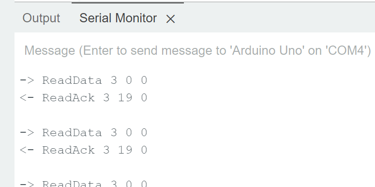
As I wrote last time, my joy did not last long because the data flew only for 1-2 hours and then it stopped. I connected WeMos to my laptop and boiler and kept it running while logging the progress to serial monitor. Eventually, it crashed (full log):


11:21:19.141 -> --------------- CUT HERE FOR EXCEPTION DECODER ---------------
11:21:19.141 ->
11:21:19.141 -> Exception (0):
11:21:19.141 -> epc1=0x402010f4 epc2=0x00000000 epc3=0x00000000 excvaddr=0x00000000 depc=0x00000000
11:21:19.141 ->
11:21:19.141 -> >>>stack>>>
11:21:19.141 ->
11:21:19.141 -> ctx: sys
11:21:19.141 -> sp: 3fffebb0 end: 3fffffb0 offset: 0190
11:21:19.141 -> 3fffed40: 3ffefa44 3ffee748 3ffee740 401001e2
11:21:19.141 -> 3fffed50: 3ffe0000 3ffeec30 3ffee740 4010041b
...
11:21:20.500 -> 3fffff90: 3fffdad0 00000000 3ffee824 401004dd
11:21:20.500 -> 3fffffa0: 3fffdad0 00000000 3ffee824 40206906
11:21:20.500 -> <<
11:21:20.500 -> --------------- CUT HERE FOR EXCEPTION DECODER ---------------
11:21:20.500 ->
11:21:20.500 -> ets Jan 8 2013,rst cause:2, boot mode:(3,6)
11:21:20.500 ->
11:21:20.500 -> load 0x4010f000, len 3460, room 16
11:21:20.500 -> tail 4
11:21:20.500 -> chksum 0xcc
11:21:20.500 -> load 0x3fff20b8, len 40, room 4
11:21:20.500 -> tail 4
11:21:20.500 -> chksum 0xc9
11:21:20.547 -> csum 0xc9
11:21:20.547 -> v000604e0
11:21:20.547 -> ~ld

The problem was that although WeMos did somehow restart, it did not pass the step that connects it again to wifi and stuck there. I had to find why it crashed.

ESP documentation shows you how to deal with crashes. I've installed Arduino ESP8266/ESP32 Exception Stack Trace Decoder and ... nothing. I just could not find it in the menu. After searching through forums, I've found out it's because I use the new Arduino IDE v2 written in Node and the decoder is a Java plugin for Arduino IDE v1. There are some ways how to make it work with v2 IDE but for me the easiest way was to install IDE v1 (1.8.19). Finally, I had the stack trace:


Exception 0: Illegal instruction
PC: 0x402010f4
EXCVADDR: 0x00000000

Decoding stack results
0x401001e2: OPENTHERM::_writeBit(unsigned char, unsigned char) at C:\Users\lucen\Downloads\Arduino\thermona.el9/opentherm.cpp line 204
0x4010041b: OPENTHERM::_timerISR() at C:\Users\lucen\Downloads\Arduino\thermona.el9/opentherm.cpp line 169
0x401004f4: timer1_isr_handler(void*, void*) at C:\Users\lucen\AppData\Local\Arduino15\packages\esp8266\hardware\esp8266\3.0.2\cores\esp8266\core_esp8266_timer.cpp line 37
0x4010053c: timer1_isr_handler(void*, void*) at C:\Users\lucen\AppData\Local\Arduino15\packages\esp8266\hardware\esp8266\3.0.2\cores\esp8266\core_esp8266_timer.cpp line 44
0x40101340: _stopPWM(uint8_t) at C:\Users\lucen\AppData\Local\Arduino15\packages\esp8266\hardware\esp8266\3.0.2\cores\esp8266\core_esp8266_waveform_pwm.cpp line 264
0x40100750: __digitalWrite(uint8_t, uint8_t) at C:\Users\lucen\AppData\Local\Arduino15\packages\esp8266\hardware\esp8266\3.0.2\cores\esp8266\core_esp8266_wiring_digital.cpp line 87
0x401001e2: OPENTHERM::_writeBit(unsigned char, unsigned char) at C:\Users\lucen\Downloads\Arduino\thermona.el9/opentherm.cpp line 204
0x401004bc: ets_post(uint8, ETSSignal, ETSParam) at C:\Users\lucen\AppData\Local\Arduino15\packages\esp8266\hardware\esp8266\3.0.2\cores\esp8266\core_esp8266_main.cpp line 181
0x401004f4: timer1_isr_handler(void*, void*) at C:\Users\lucen\AppData\Local\Arduino15\packages\esp8266\hardware\esp8266\3.0.2\cores\esp8266\core_esp8266_timer.cpp line 37

But I was not clever from it... What illegal instruction during sending data to boiler? It's worth to note my knowledge about C++ is almost zero and the same applies for Arduino/WeMos HW. So I was not really sure what I need to look for...

I've enabled all compiler warnings in IDE Preferences and saw a warning about ICACHE_RAM_ATTR deprecation in favor of IRAM_ATTR. I have updated it in OpenTherm library but program still crashed. So I continued to search through forums. 

Soon, I've found this StackOverflow question about ISR (Interrupt Service Routine) and why IRAM_ATTR attribute is needed. It did not ring the bell for me. Retrospectively, it should especially if I read it more carefully but I didn't and thus still not understand the issue. I just knew it has something to do with interrupts, functions not available in memory. Few hours forward and I found great blog post by Chris Dzombak: Debugging an Intermittent Arduino/ESP8266 ISR Crash. I had the same reset reason (rst cause:2, boot mode:(3,6)) and Chris explained his investigation so well that even I have finally understand it.

I've went through all functions that were called from OPENTHERM::_timerISR() method and add IRAM_ATTR attribute. I uploaded it to WeMos and ran it. It did successfully pass 2 hours timestamp. But it crashed again after about a day. Looking at the new crash I saw almost the same stack trace. I gave up and added IRAM_ATTR attribute to all private methods and public send method (code). Since then, the data has been flowing flawlessly for couple of days now, so it seems the problem has been fixed!

Monday, January 2, 2023

Quest for lower electricity consumption - WeMos D1 Mini R2

WeMos D1 Mini is an ESP8266 WiFi board compatible with Arduino. OpenTherm shield and library should support it so switch from Arduino Uno should be easy... Of course, it was not :-)

First let's wire it correctly. I've seen complain on github it does not work with some pins. Here is my wiring which works for me:
  • OpenTherm jumper set to 3.3V
  • OpenTherm D3 - WeMos D1 (via header) : #define BOILER_IN 5
  • OpenTherm D5 - WeMos D5 (via header) : #define BOILER_OUT 14
  • OpenTherm 3.3V - WeMos 3.3V
  • OpenTherm GND - WeMos GND

Picture which shows both leds blinking (ON and RxB leds) - proof it works:


If you, for example, connect 5V from WeMos to 5V on OpenTherm shield, it will not work (it took me almost an hour to figure it out).

My code is based on examples how to connect to wifi, use https client and send a POST request (you can easily open them from Arduino IDE  via menu File - Examples - ESP8266HTTPClient).

Data for every message type is sent to a webhook in Home Assistant (message id is suffix in webhook name). Sensor configurations are straightforward except conversion of bit mask to binary sensor:

template:
  - trigger:
      - platform: webhook
        webhook_id: boiler0
    sensor:
      - name: Boiler - updated at
        unique_id: boilerupdate
        state: "{{ as_timestamp(now())|timestamp_custom('%d. %m. %Y %H:%M:%S') }}"
        icon: mdi:clock-time-four-outline
    binary_sensor:
      - name: Boiler - error
        unique_id: boiler0fault
        state: "{{ trigger.json.data|int|bitwise_and(1) > 0 }}"
        device_class: problem
      - name: Boiler - central heating
        unique_id: boiler0ch
        state: "{{ trigger.json.data|int|bitwise_and(2) > 0 }}"
        device_class: running
      - name: Boiler - warm water
        unique_id: boiler0dhw
        state: "{{ trigger.json.data|int|bitwise_and(4) > 0 }}"
        device_class: running
      - name: Boiler - heating
        unique_id: boiler0flame
        state: "{{ trigger.json.data|int|bitwise_and(8) > 0 }}"
        device_class: running
  - trigger:
      - platform: webhook
        webhook_id: boiler18
    sensor:
      - name: Boiler - pressure
        unique_id: boiler18
        state: "{{ trigger.json.data }}"
        state_class: measurement
        device_class: pressure
        unit_of_measurement: bar
        icon: mdi:speedometer
...
Using all sensors, I've created a dashboard in Home Assistant to have a full picture how the boiler works :


But my joy did not last long - within 1-2 hours, the data stopped flowing :-( Next post will be about figuring why?

PS: The above image is from future when the issue is fixed.

Friday, December 30, 2022

Quest for lower electricity consumption - OpenTherm

The first article ends by the need to get more data from boiler because it heats warm water too often.

The first step I did was actually disabling circulating warm water every 15 minutes which I used to have always warm water immediately instead of waiting until it reaches a tap. Surprisingly, I observe almost no difference. There is still quite warm water immediately in the tap but the boiler heats water with the same frequency...

My home heating setup consists of two main heating branches - one with central heating (additionally split to radiators and floor heating) and the second with external tank for warm water. For some reason there is no three-way valve to stop flowing water to external tank when running in central heating mode. I suspect this is the culprit why boiler heats external tank approximately every two hours. To confirm it, I need data about what mode the boiler runs (although it can be guessed from the power consumption) and temperature in the external tank which triggers its heating. All can be retrieved via OpenTherm protocol.

OpenTherm standard is designed for communication between boiler and thermostat. Mine boiler - Thermona Therm EL 9 - does support it.

Googling how to get data from OpenTherm resulted in several links:

  1. https://www.home-assistant.io/integrations/opentherm_gw/
    Hurray - there is a way how to get data to Home Assistant!
  2. http://otgw.tclcode.com/ - the gateway. Unfortunately, it looks quite complex...
  3. https://github.com/jpraus/arduino-opentherm - library for Arduino by Jiří Praus with his HW looks much easier to use and I went for this option.
  4. Only later I have found out it would be enough to use https://ihormelnyk.com/opentherm_adapter (because I don't need to communicate with thermostat).
I have ordered OpenTherm Gateway Arduino Shield. I struggled to find 24V power supply, even wrote to Jiří who quickly suggested GME but eventually I've ordered it from Tipa. Soldering it together was a challenge as I have soldered only big electronic parts till now. Because of my "huge" experiences, I've managed to solder headers upside down so I need to use wires to connect it to Arduino Uno for testing.

Eventually, I was able to put everything together and test the hardware, interfaces and self-test. All tests have passed. The only issue/difference I saw was in step 6 where I measured ~4.7V instead of 5-7V.

Here is the wiring because it was not obvious for me; pin constants in code are the same:
  • OpenTherm jumper set to 5V
  • OpenTherm D3 - Uno D3 (via header) : #define BOILER_IN 3
  • OpenTherm D5 - Uno D5 (via header) : #define BOILER_OUT 5
  • OpenTherm 5V - Uno 5V
  • OpenTherm GND - Uno GND

Having wired the OpenThem shield with Arduino, next step was to get data from boiler using sample code. The code uses arduino-opentherm library which needs to be put into Arduino IDE Sketchbook library folder (e.g. C:\Users\{username}\Documents\Arduino\libraries\arduino-opentherm on Windows).


It worked! Going through OpenThem 2.2 specification, I've identified useful messages for my boiler:
  • OT_MSGID_STATUS - boiler's status (what does it heat)
  • OT_MSGID_FAULT_FLAGS - current fault code
  • OT_MSGID_MODULATION_LEVEL - boiler's power (0-100%)
  • OT_MSGID_CH_WATER_PRESSURE - boiler's water pressure
  • OT_MSGID_FEED_TEMP - boiler's water temperature
  • OT_MSGID_DHW_TEMP - warm tank's water temperature
  • OT_MSGID_OUTSIDE_TEMP - outside temperature (for equithermal regulation)
  • OT_MSGID_DHW_SETPOINT - target water tank temperature
Next step is to switch from Arduino Uno to WeMos D1 so I can send the data wirelessly to my Home Assistant.

Thursday, December 29, 2022

Quest for lower electricity consumption - Measurement

With electricity prices skyrocketing this year, I've started looking into ways how to save some money by lowering electricity consumption. The first step is of course measurement!

I use Shelly Plus 2PM to control my external blinds so the choice was obvious - use Shelly 3EM. To get some idea how installation looks like, I watched Shelly 3EM Installation video by Jimmy James. Based on that, I've decided I can handle it myself.

Shelly 3EM Installation
The problem was space in our electrical cabinet. Because it's not only 1 spot for the meter but another 3 for the circuit breaker and place around input wires to put clamps. Eventually, I've hacked it for the beginning and put the circuit breaker outside of the cabinet. Just to see whether the meter works fine.


It does! Of course, later I plan to make it nicer and hide the cables into the wall.

Setup Shelly 3EM In Home Assistant
Setup in Shelly web interface is easy - I just restricted access for admin, configured wifi and added Device name - I called in Main Power so it will look good in Home Assistant. Then I added the Shelly integration to my Home assistant which configured automatically all sensors. I remember small hick-up with discovering the device - you need to enter just IP address and then it will ask you for user/password (I was trying to add http://IP which does not work).


Later I have updated Shelly settings based on recommendation for generation 1 devices and set ColoT peer directly to my Home assistant IP address. It seems to me it speeds up updates in Home Assistant.


Energy Dashboard
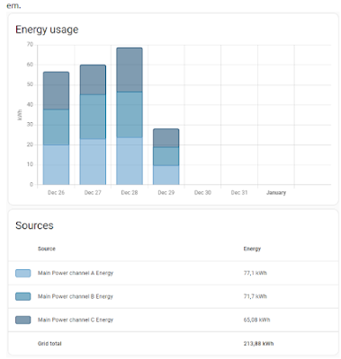
For Energy dashboard in Home assistant, I just added all three channels/phases as Grid consumption - it nicely shows the consumption split by them.


Detailed Energy Graphs
To see detailed consumption, first I set up Total Power sensor in configuration.yaml (based on Jimmy video):

template:
    - name: Total Power
      unique_id: total_power_tmpl
      unit_of_measurement: W
      state_class: measurement
      device_class: energy
      state: >
        {% set phase1 = states('sensor.main_power_channel_a_power') | float %}
        {% set phase2 = states('sensor.main_power_channel_b_power') | float %}
        {% set phase3 = states('sensor.main_power_channel_c_power') | float %}
        {{ phase1 + phase2 + phase3 }}
And then using apexcharts-card graphs, I've set up cards showing consumption in the last hour, 6 hours, etc.

type: custom:apexcharts-card
graph_span: 1h
header:
  show: true
  title: Energy 1h
all_series_config:
  stroke_width: 1
series:
  - entity: sensor.total_power
    name: Total
    color: rgb(162, 185, 207)
  - entity: sensor.main_power_channel_a_power
    name: Phase A
    color: rgb(3, 169, 244)
  - entity: sensor.main_power_channel_b_power
    name: Phase B
    color: rgb(128, 233, 234)
  - entity: sensor.main_power_channel_c_power
    name: Phase C
    color: rgb(255, 191, 128)

The big spikes on 6h graph are when our boiler heats tank with warm water. The problem is it does it every ~2 hours even during night which is too often and thus costly…

The next part is to find out more data from the boiler.